
Cross-Hole testing consists of measuring the travel time of compression (P) and shear (S) seismic waves between several boreholes. It enables us to determine, depending of the depth, their seismic velocities, Vp and Vs, as well as geodynamic parameters (Young’s modulus E, shear modulus G, and Poisson’s ratio n).
With the shear wave velocity Vs, if the boreholes are deep enough, we can determine the average shear-wave velocity in the first 30 meters, as defined by the Eurocode 8.
Down-Hole testing is a variant of Cross-Hole testing, in which a seismic wave is generated at the surface, near the borehole, in which the arrivals of the compression and shear waves are measured. The surface source is specially adapted to generate shear waves and compression waves. Results interpretation and restitution are similar to those for Cross-Hole testing. In case of a clear anisotropy, parameters determined this way can be notably different from parameters determined by Cross-Hole testing.
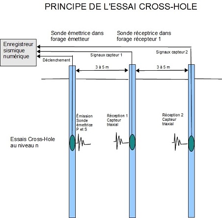
In general, tests are carried out from the surface to the bottom of the boreholes. The step varies depending on the goal of the study, but it is typically 1 to 5 meters long according to the borehole depth and the strength of the geologic strata. We carry out measurement between a seismic transmitter probe placed in a « transmitter » borehole, and one or several receiver probe placed at the same depth in “receiver” boreholes. The test is ideally carried out with three boreholes placed in line so as to measure the compression and shear waves velocity by difference between the two receiver boreholes, avoiding the source which might generate errors in the measures. However, in many cases only two boreholes are used.
The seismic source, located in the “transmitter” borehole, comprises a mobile seismic mass and a pneumatic sticking system. By hitting alternatively upwards and downwards, the source produces alternatively a polarised S wave upwards and then downwards at the same time as the P wave which is not polarised. Thus, the S wave is better identified in the wave train. The mass and the probe are equipped of a trigger sensor, connected to the recorder, allowing the synchronisation of the impact with the trigger of the recording.
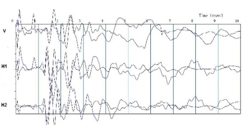
Seismic waves are measured in « receiver » boreholes using a seismic receiver probe also stuck on the borehole via an anchoring system. The probes consist of three sensors, all oriented at 90° from each other (one vertical and two horizontal at 90° from one another). This layout allows, during Cross-Hole testing, a good identification of the S wave trains, acting principally on the vertical sensors, and of the P wave trains, putting principally a strain on the horizontal sensors. The opposite happens during Down-Hole tests. The receiver probes are connected to the seismic recorder via a measuring cable. The measures are taken at different depths, typically every 1, 2 or 3 meters, so as to get a cross section of P and S waves velocities as a function of the depth.
The figure below gives an example of a recording at a given depth. The geodynamic parameters are then calculated using the following relations:
Young’s Modulus, in MPa : E = 2 r Vs² (1 + n)
Shear modulus, in MPa : G = r Vs²
Poisson’s ration, number without unit : n = (Vp²-2Vs²) / 2 (Vp² – Vs²)
Vs,30 = 30/ S Hi/Vs,i with Hi, Vs,i thickness and velocity Vs of the layer i on the first 30 meters
Vp and Vs are respectively the compression and the shear waves velocities and are expressed in meter per second (m/s). To calculate E and G, we need to know or hypothesise on the density r of the crossed ground.
Except when the borehole is made in a rock land and does not constitute a risk of rock slide or of trapping the probe, PVC protection tubes need to be inserted in the boreholes before placing the probe during Cross-Hole and Down-Hole testing. The tubes, of diameter lower than 80mm and 4 to 5 mm thickness, need to be fixed to the borehole side walls with cement grout on the whole height. They must be blocked at the bottom and watertight. Connections between the tubes have to be screwed and glued. Part of the quality of test results depends of the quality of the seal. The tests can be done at the earliest a week after drilling the boreholes so that the grout reaches a sufficient mechanical resistance. Measures of borehole deviation are carried out at the same time as Cross-Hole testing to know precisely the distance between the source and the sensors at each test level.